Sản phẩm
Rơ le bảo vệ – Châu Âu

Thông tin sản phẩm
Thông số kỹ thuật
DRAGON FAMILY
Company VINNOTEK is a leader in Protection Control and Automation technologies that enables utility and industry customers to improve performance and reliability of their network system. VINNOTEK provides modern solutions for T&D network, Industrial and Distribution Generation objects. DRAGON family comprises a wide range of world-class numerical Protection relays, Bay control units (BCUs), Annunciators and Transformer Monitoring & AVR systems.
| VINNOTEK Multifunction Protection Relays
The great focus today is high-quality cost-effective intelligent Electronic Devices (IEDs) that help power producers and distributors. Our aim is to assist them in achieving results in most efficient way. The newest member of VINNOTEK IEDs is DRAGON family that combines a lot of “State of the art” decisions in a single IED with flexible construction and potentialty. · Simple, cost-effective and compact design with fully integration of all neessary protection and control functions; · Midular construction that allows flexible extension of I/Os; · EMC, Insulation, Mechanical and Climatic type tests according to the current IEC/EN standards; · High avaliability with less maintenance because of the efficient self-monitoring. · 80 samples per cycle scan-rate; · Local Human Machine Interface (HMI) through the front panel keypad, LEDs and LCD numerical/graphical display; · Simple and user friendly PC based Man Machine Interface (MMI) dialog; · Configuration and settings via portable PC and MS Windows compatible service MMI program (single program for the entire family); · IEC 61131 flexible programming allowing new protection and control functions to be added without any influence on the physical wiring; · Variety of time synchronization protocols: SNTP, IEEE1588 (PTPv2), IRIG-B, 1PPS; · Communication with SAS upper level via different interfaces including Ethernet LAN with electrical / fiber optic connections; · Communication protocols according to IEC 61850 ed1/ed2, IEC 60870-5-104, IEC 60870-5-103, DNP-3 and Modbus RTU/TCP; |
· Redundancy protocols IEC 62439-3 (PRP/HSR), RSTP
· Integration of Power Transformer “condition monitoring” and AVR functionalities including life time supervision; · Fully application of Digital substation concept including availability of IEC 61850 based Process bus, Merging units and Intelligent I/O boxes Application DRAGON family includes a lot of protection functions for different applications: · Main and/or backup protection for overhead lines, underground cables, transformers, motors and Busbar; · Suitable for EHV, HV and MV network; Industry, Transport, Distribution Generation (Wind farms, Solar parks etc.). · Applicable for all types of neutral grounding (isolated, solid, resistace or resonance);
DRAGON family Protection and control devices Feeder protection – Overcurrent protection and control RFI D Line protection – Distance protection and control RLI Dd – Differential and Distance protection an control RLI DI Transformer protection – Transformmer differential protection and control RTI D Motor protection – Motor differential protection and control RMI D Busbar protection – Centralized Busbar protection RBP Dc – Decentralized Busbar protection RBP Dd |
| Bay control unit
– Bay controller with control and monitoring RTU D – Bay controller with control, monitoring and protection (optional) RTU Dp
Transformer monitoring and AVR set RTU Dt RTU Dt set is applicable for medium and large oil immersed power transformers with Onload tap changers (OLTC). The set provides safe, reliable, easy to use and cost effective power transformer condition monitoring and AVR functionality. The set is equipped with remote modules which are suitable for indoor and outdoor installation near to the Power Transformer.
Voltage regulation functionality provides: · Automatic and manual OLTC control of a single power transformer · Automatic and manual OLTC control of parallel operating power transformers · Three-phase overcurrent and under / over voltage blocking In case of parallel operating transformers RTU Dt is able to communicate via IEC 61850 GOOSE messages (IEC 61850-81 protocol). Complete exchange of the necessary voltage control data-analogue as well as binary, is executed via GOOSE.
Annunciator RAU D RAU-D is designed to be used for alarm and warning signalization in Conventional and Digital substation automation projects. RAU-D is able to support IEC 61850 and to be part of SAS.
Hardware Basic (1/2 19”) and extended (1/1 19”) construction with graphical display – see Fig. 1 and Fig.2. Alpha – numerical display is also available. |
TECHNICAL DATA
| No | FUNCTIONS | IEC 61850 | ANSI | Line Differential & Distance Protection | Transformer Protection | Feeder Protection | Motor Protection |
| 1 | Protection | ||||||
| 1.1 | Distance protection – 5+1 zones | PDIS | 21/21N | ● | |||
| 1.2 | Directional DT/IDMT Overcurrent protection | PTOC | 50, 51, 67 | ● | ● | ● | ● |
| 1.3 | Directional DT/IDMT Earth fault protection | PTOC | 5ON/5IN/67N | ● | ● | ● | ● |
| 1.4 | Group Instantaneous overcurrent protection | PTOC | ● | ||||
| 1.5 | 1-pole/3-pole multi-shot Autoreclosing | RREC | 79 | ● | ● | ||
| 1.6 | Sensitive Directional Earth fault protection Wattmetric/Admitance | PSDE | 67Ns | ● | ● | ● | ● |
| 1.7 | Transient/Intermittent earth fault protection | PTEF | 67NIEF | ● | ● | ||
| 1.8 | High harmonics content earth fault protection | PTOC | 51NHA | ● | |||
| 1.9 | Cold load pick-up | 51C | ● | ● | |||
| 1.10 | Thermal overload protection | PTTR | 49 | ● | ● | ● | ● |
| 1.11 | Phase discontinuity l2/l1 detection | PTOC | 46PD | ● | ● | ● | ● |
| 1.12 | ARC protection | SARC | ● | ● | ● | ● | |
| 1.13 | Negative-sequence Overcurrent protection | PTOC | 46 | ● | ● | ● | ● |
| 1.14 | Definite time under current protection | PTUC | 37 | ● | ● | ● | |
| 1.15 | Starting time supervision | PMSS | 48 | ● | |||
| 1.16 | Loss of load protection | PTUC | 37 | ● | |||
| 1.17 | Number of starts limitation | PMRI | 66 | ● | |||
| 1.18 | Stalled rotor protection | PRTR | 51LR | ● | |||
| 1.19 | Cooling system failure protection | CCGR | ● | ||||
| 1.20 | Directional over/under power protection | PDOP/PDUP | 32/37 | ● | ● | ● | ● |
| 1.21 | Motor differential protection | PDIF | 87M | ● | |||
| 1.22 | Breaker failure protection | RBRF | 51BF | ● | ● | ● | ● |
| 1.23 | Pole discordance protection | QIUB | 52PD | ● | ● | ● | ● |
| 1.24 | Over/under voltage protection | PTOV/PTUV | 59/27 | ● | ● | ● | ● |
| 1.25 | Neutral voltage displacement protection | PTOV | 59G | ● | ● | ● | ● |
| 1.26 | Positive sequence over/under voltage protection | PTOV/PTUV | 47O+/47U+ | ● | ● | ● | ● |
| 1.27 | Negative sequence overvoltage protection | PTOV | 47O | ● | ● | ● | ● |
| 1.28 | Over/under frequency protection | PTOF/PTUF | 81O/81U | ● | ● | ● | ● |
| 1.29 | Rate of frequency change | PFRC | 81R | ● | ● | ● | |
| 1.30 | Voltage vector shift | ● | |||||
| 1.31 | Line differential protection | PDIF | 87L | ● | |||
| 1.32 | Transformer differential protection | PDIF | 87T | ● | |||
| 1.33 | Restricted earth fault protection | PDIF | 87N | ● | ● | ||
| 1.34 | Overexcitation protection | PVPH | 24 | ● | |||
| 1.35 | Loss of excitation (loss of field) | PVPH | 40 | ● | |||
| 1.36 | Low impedance Busbar differential protection | PDIF | 87BB | ||||
| 1.37 | User defined logical functions | ● | ● | ● | ● | ||
| 2 | Measurement and calculation | ||||||
| 2.1 | Phase currents true RMS | MMXU | ● | ● | ● | ● | |
| 2.2 | Fundarmental (1st harm.) current | MSQI | ● | ● | ● | ● | |
| 2.3 | Residual current 3lo | MMXU | ● | ● | ● | ● | |
| 2.4 | Current in the neutral | MMXU | ● | ● | |||
| 2.5 | Positive sequence current l1 | MSQI | ● | ● | ● | ● | |
| 2.6 | Negative sequence current l2 | MSQI | ● | ● | ● | ● | |
| 2.7 | Phase voltage | MMXU | ● | ● | ● | ● | |
| 2.8 | Phase to phase voltage true RMS | MMXU | ● | ● | ● | ● | |
| 2.9 | Fundamental (1st harmonic) voltage | MSQI | ● | ● | ● | ● | |
| 2.10 | Residual voltage 3Uo | MMXU | ● | ● | ● | ● | |
| 2.11 | Positive sequence voltage U1 | MSQI | ● | ● | ● | ● | |
| 2.12 | Negative sequence voltage U2 | MSQI | ● | ● | ● | ● | |
| 2.13 | Frequency f | MMXU | ● | ● | ● | ● | |
| 2.14 | Rate of frequency df/dt | MMXU | ● | ● | ● | ||
| 2.15 | Active, Reactive and Apparent power | MMXU | ● | ● | ● | ● | |
| 2.16 | Current-voltage angle, cos ɸ | MMXU | ● | ● | ● | ● | |
| 2.17 | Energy measurement | MMTR | ● | ● | ● | ● | |
| 2.18 | 2nd to 15th harmonic and THD | MHAI | ● | ● | ● | ● | |
| 2.19 | Temperature | STMP | ● | ● | |||
| 3 | Monitoring and control | ||||||
| 3.1 | Fault locator | RFLO | 21FL | ● | ● | ||
| 3.2 | Trip circuit supervision | SSWI | 74TC | ● | ● | ● | ● |
| 3.3 | Current circuits symmetry / sum monitoring | TCTR | TCN | ● | ● | ● | ● |
| 3.4 | Voltage circuits / fuse failure monitoring | TVTR | 60 | ● | ● | ● | ● |
| 3.5 | Primary eqiupment local remote control | CSWI | ● | ● | ● | ● | |
| 3.6 | Circuit breaker condition monitoring | SCBR | CBCM | ● | ● | ● | ● |
| 3.7 | Lockout logic / Latching Acknowledgement | 86 | ● | ● | ● | ● | |
| 3.8 | Clockwise and anticlockwise phase rotation monitoring | ● | ● | ● | ● | ||
| 3.9 | Min/max and average values monitoring – I, U, P, Q, S cos ɸ | MMXU | ● | ● | ● | ● | |
| 3.10 | Uper/lower limits monitoring – – I, U, P, Q, S cos ɸ | ||||||
| 3.11 | Temperature monitoring | TTMP | ● | ● | |||
| 3.12 | Synchronism check | RSYN | 25 | ● | ● | ||
| 3.13 | Signalization | ● | ● | ● | ● | ||
| 4 | Recorders | ||||||
| 4.1 | Event/fault recorder | ● | ● | ● | ● | ||
| 4.2 | Disturbance recorder | RADR | ● | ● | ● | ● | |
| 5 | Additional functions | ||||||
| 5.1 | Pc-based Man Machine interface service program (MMI) | ● | ● | ● | ● | ||
| 5.2 | Time Synchronisation – date communication channel | LTIM | ● | ● | ● | ● | |
| 5.3 | Self supervision with internal event list | ● | ● | ● | ● |
TECHNICAL DATA
| No | TECHNICAL DATA |
| 6 | Hardware* |
| 6.1 | Power supply 110-220VDC/VAC, 24-72VDC/VAC, 220VDC/VAC (-20%+20%) |
| 6.2 | Phase current 1A/5A, 0.1 – 40 In |
| 6.3 | Phase current 1A/5A, 0.01 – 1.6 In |
| 6.4 | Residual current – sensitive 0.2A, 0.1 – 40 Ion |
| 6.5 | Voltage inputs 100/110V (phase-phase/3Uo) 0.005 – 2.00 Un |
| 6.6 | Binary inputs 220VDC, 110VDC, 48VDC, 24VDC, 220VAC, 110VAC (±20%) |
| 6.7 | Binary outputs, Switching voltage 250VDC/VAC |
| 6.8 | Real time clock |
| 6.9 | Keypad and display – graphical 640×480 dot matrix or 4 x 20 LCD |
| 6.10 | LED indication – 24 LEDs |
| 6.11 | Dimensions ½ x 19” (WxHxD) 225/266/133 – max weight 3.4 kg |
| 6.12 | Dimensions 1×19” (WxHxD) 465/266/133 – max weight 5.2 kg |
| 7 | Communication Interfaces** |
| 7.1 | Electrical Ethernet 100BASE-TX – RJ45 connector |
| 7.2 | Optical Ethernet 100BASE-FX – LC connector, ST connector |
| 7.3 | Electrical RS485 |
| 7.4 | Real time synchronization IRIG-B – coaxial cable BNC connector or FO MM ST connector |
| 7.5 | IEEE C37.94/G704, ST or LC connectors for Line differential protection |
| 7.6 | RJ45 front panel interface for communication with PC loaded MMI program |
| 7.7 | PPS input – coaxial cable BNC connector of FO MM ST 820mm |
| 8 | Communication protocols** |
| 8.1 | IEC 61850 ed1/ed2 |
| 8.2 | IEC 61850-9-2LE |
| 8.3 | IEC 60870-5-103 |
| 8.4 | IEC 60870-5-104 |
| 8.5 | Modbus RTU/TCP, DNP 3.0 RTU/TCP |
| 8.6 | SNTP/PTP/IRIG-B/PPS |
| 8.7 | FTP |
| 8.8 | Web-server HTTP |
*For the number of current and voltage inputs and binary inputs and outputs – see the respective Ordering vector in www.vinnotek.de.
**For the different sets of communication interfaces and protocols – see the respective Ordering vector in www.vinnotek.de.
Bình luận
Sản phẩm liên quan


Giải Pháp Thiết Bị Cho Hạ Tầng Giao Thông, Pha Giải phóng mặt bằng, Phá Dỡ & Chỉnh Trang Đô Thị
Mã: MQTEK.AM.01


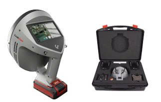
Camera Siêu Âm Phát Hiện Rò Rỉ Khí Nén – Công Nghệ Đức – Acoustic Camera for Compressed Air Leak Detection – German Technology
Mã: MQTEK.LEKCAM.01


Ron Cao Su EPDM Cao Cấp – Giải Pháp Chống Ồn, Cách Nhiệt & Kín Khít Đa Ứng Dụng
Mã: MQTEK.GIOĂNG.AUTO